
Primary Authors: Lindi Moore and Peter Reim. Oversight, Review, and Final Edits by Vi Dinh (POCUS 101 Editor).
Shoulder pain is a very common complaint, with a lifetime prevalence as high as 67% (Hodgetts et al., 2021). Although etiologies are broad, the most common origins of shoulder pain arise from the long head biceps tendon, the acromioclavicular joint, the subacromial bursa, and the muscles of the rotator cuff. Thankfully, ultrasound offers a simple, safe, and inexpensive tool to quickly assess the shoulder.
In this article we will utilize the A.S.A.P step-by-step protocol to systematically perform ultrasound of the shoulder. We will cover:
- Anatomy of the shoulder
- Step-by-step maneuvers to obtain the desired views
- Pathology seen at each view
- Therapeutic ultrasound-guided injection/aspiration procedures that are commonly performed
By the end of this article, readers will be able to statically and dynamically assess each muscle, bursae, and joint, and identify pathology within each structure. Additionally, readers will know how to perform common ultrasound-guided therapeutic procedures.
Table of Contents
Shoulder Ultrasound Pocket Card (FREE DOWNLOAD!)

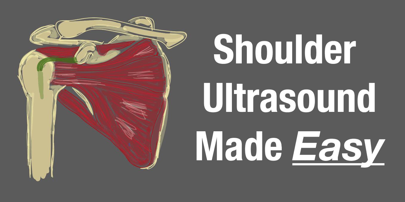
Shoulder Ultrasound Anatomy
The shoulder joint (AKA Glenohumeral Joint) is made up of the head of the humerus which sits within the glenoid fossa. The fossa is surrounded by the glenoid labrum which is a fibrocartilaginous rim that stabilizes the head of the humerus within the glenoid fossa. Damage to the labrum causes instability and pain. The labrum is surrounded by a fibrous joint capsule known as a bursa that is lined by a synovial membrane which produces fluid that reduces friction within the joint. There are several additional bursae within the shoulder joint. The most important bursa for our discussion of shoulder pain is the subacromial-subdeltoid bursa (SASD) located deep to the acromion and deltoid but superficial to the supraspinatus.

The glenohumeral joint is further stabilized by multiple muscles and tendons which are responsible for the wide range of motion of the healthy shoulder. The humeral head has two attachment protuberances, the greater and lesser tubercles, divided by the intertubercular groove where the LHBT runs. The greater tubercle is further defined by three facets that serve as attachment points for three the rotator cuff muscles.
The collection of four rotator cuff muscles (supraspinatus, infraspinatus, subscapularis, and teres minor) originate from the scapula and insert at the humeral head. Three muscles attach to the greater tubercle along the three different facets. The supraspinatus (abduction) attaches to the superior facet, the infraspinatus (external rotation) attaches to the middle facet, and the teres minor (external rotation) attaches to the inferior facet. The subscapularis (internal rotation) attaches to the lesser tubercle. When damage occurs to any of these muscles, patients may present with significant shoulder weakness, pain, or instability. Knowing where these muscles insert is key to identifying pathology during the ultrasound examination.
Another aspect of the shoulder is the acromioclavicular joint which is just superior to the shoulder joint where the acromion meets the distal end of the clavicle. Although it is not a part of the intrinsic shoulder joint like the other structures mentioned above, it’s anatomical relation to the shoulder joint and associated muscles make it important to include in the exam.


Patient Preparation
If available, the patient should be placed on a rotating stool so that the examiner can remain in place throughout the examination. Alternatively, the patient can be seated off the side of an examination table near the foot of the bed. The shoulder in question should be closest to the examiner. Pay attention to the patient height in relation to the examiner. The examiner should be standing with their shoulder above the patient’s shoulder with their arm relaxed (not overextended across the patient).
Machine Preparation
Transducer: Most exams will utilize the Linear 10-12MHz probe. The Curvilinear 9MHz probe may be necessary if the patient has a large amount of soft tissue.
Preset: MSK
Indicator Orientation: It can be confusing knowing how to orient the probe when moving between anterior and posterior examinations. When examining the anterior shoulder, the indicator should point toward the patient’s right. When transitioning to the posterior shoulder, the indicator will now point toward the patient’s left.
Note: In each image there will be a red arrow indicating the position of the indicator to help with correct placement.
Terms: Short-axis will be used to refer to probe orientation in relation to the orientation of the target anatomy. Long-axis will be used to refer to the indicator orientation parallel to the orientation of the target anatomy. Oblique-axis will be used to refer to the 600 angle that is used when evaluating the anterolateral portion of the shoulder.
Shoulder Ultrasound Exam – The A.S.A.P. Protocol
We will be using the organization method developed by RSNA (Radiologic Society of North America) to guide our examination. Think A.S.A.P. – Anterior, Superior, Anterolateral, Posterior. The table below outlines the examination. We will go through each view in a step-by-step process and talk about pathology seen at each view.
| Shoulder Region | Structures Seen | Arm Positioning | Dynamic Evaluation |
| ANTERIOR | Long head of Biceps Tendon | Elbow flexed at 900 | Internal and external rotation with the elbow bent at 900 |
| Subscapularis | Elbow flexed at 900 with forearm externally rotated | None | |
| SUPERIOR | AC Joint | Forearm and hand laying on the ipsilateral thigh | Keep the elbow fixed to side. Have patient reach the ipsilateral hand to contralateral shoulder |
| ANTEROLATERAL | Supraspinatus and Subacromial-Subdeltoid Bursa | Modified Crass or internal rotation | Have the patient abduct the arm away (check for supraspinatus impingement) |
| POSTERIOR | Infraspinatus (IST), Teres Minor (TM), Posterior Labrum, and Spinoglenoid Notch | Forearm and hand resting palm up on the ipsilateral leg | None |
Anterior: The LHBT and the Subscapularis
The Long Head Biceps Tendon (LHBT)
Short-Axis (LHBT)
- Position: Have the patient flex their elbow at 900 with the palm facing up.
- Probe: Place the transducer in the short axis along the bicipital groove. The long head of the biceps brachii sits within the bicipital groove.
- Slide the probe proximal to distal to the myotendinous junction where the pectoralis major tendon is seen.
- Look For
- Evidence of subluxation with the LHBT displaced out of the groove.
- Hypoechoic defects in the groove indicating tendon rupture.
- Thickening or effusion surrounding the LHBT within the groove.
- Note: The biceps tendon courses deep as it moves distally, so it may be helpful to fan the tail of your probe inferiorly in order to keep the ultrasound perpendicular and prevent anisotropy.


Long-Axis (LHBT)
- Probe: Rotate the transducer 900 to evaluate the long head of the biceps in the long axis.
- Indicator: The indicator will be pointing superiorly in the longitudinal axis.
- Again, the tendon courses deep so you may have to rock the probe tail inferiorly in order to prevent anisotropy.
- Note: This view is more limited when compared to the short axis view.


Dynamic Scan
- Probe: Return to the short axis.
- Action: Have the patient internally and externally rotate their arm while you evaluate the tendon in its groove.
- Goal
- Look for any evidence of subluxation or dislocation visualized as the hyperechoic tendon sliding medically or laterally out of the groove, leaving a hypoechoic defect.
The Subscapularis
Long Axis
- Position: Have the patient externally rotate their forearm, palm up, while keeping the elbow fixed at their iliac crest.
- Probe: Return to the short axis view of the LHBT.
- Look For
- Fibrillar articulations of the tendon
- Hyperechoic calcifications
- Hypoechoic effusion
- Flattening of the contour
- Note: In this orientation, the subscapularis is commonly striated where muscle and tendon bundles interarticulate. Do not confuse this with a real pathology.


Short Axis
- Probe: Rotate the probe 900 into the transverse view.
- Indicator: The indicator should be pointing superiorly
- Slide the probe superior to evaluate the lesser tubercle and then inferiorly to evaluate the entire length of the tendon.
- Look For
- Evidence of effusion
- Hypoechoic defects within the muscle


Superior Exam: The Acromioclavicular Joint
The Acromioclavicular (AC) Joint
Short Axis
- Position: The patient with their elbow by their side, bent at a 900 angle and the forearm and hand laying along the ipsilateral thigh.
- Probe: Palpate medially → laterally along the clavicle until the acromioclavicular notch is appreciated near the shoulder.
- Indicator: Place the probe so that the indicator is toward the patient’s right in the axis of the clavicle. The middle of the probe should be directly over the AC notch.
- Look For
- Increased echogenicity
- Irregular margins
- Fluid collections


Dynamic Scan
- Action: Have the patient reach for the opposite shoulder with the ipsilateral arm, keeping the elbow bent and close to the body.
- Probe: Keep the probe in the same placement as the static exam.
- Goal
- Assess for instability and abnormal width > or < 3mm of the joint space as the patient’s arm is abducting across their body to the contralateral shoulder.


Anterolateral Exam
The Supraspinatus, Subacromial Subdeltoid Bursa, and Rotator Interval
Oblique Longitudinal Axis
- Position: Place the patient in the modified CRASS Position: ipsilateral hand, palm flat against the posterior iliac spine with elbow directed posteriorly.
- Probe: Place the probe over the anterior shoulder in a longitudinal/oblique-axis that is parallel to the humerus.
- Indicator: Pointing obliquely towards the top of patient’s head.
- Slide the probe slightly laterally to visualize the LHBT in the rotator interval between the acromion and the greater tuberosity.
- Look For
- Hypoechoic defects indicating a supraspinatus tear (These may be limited to the anterior portion adjacent to the LHBT)
- Effusions of the subacromial subdeltoid bursa adjacent to its border near the greater tuberosity
- Thickening or calcifications of the articular cartilage
- Make sure to visualize the attachment of the supraspinatus to the superior facet
- Note: The transition to the middle facet which can be identified by an apparent flattening of the facet and a greater angle between the humeral head and facet surface.


Long Axis
- Probe: Rotate the probe 900 for a long-axis/oblique evaluation of the SST.
- Indicator: Indicator should now be pointed obliquely towards the tip of the patient’s shoulder.
- Begin proximally along the humeral head, and, again, ensure that the LHBT is in view. Move distally until the edge of the superior and middle facet are in view.
- Note: The goal of this exam is to focus on the SST. The IST will be visualized partially as you examine the middle facet, but will be more completely examined in the posterior examination (see below).


Dynamic Scan
- Probe: Place the probe in the long axis of the humerus at the lateral edge of the acromion.
- Action: Passively or actively abduct the ipsilateral arm evaluating the movement of the supraspinatus tendon (depending on ability or pain).
- Goal
- Check for impingement.
- If the tendon slides smoothly and disappears under the acromion it is normal. If the tendon appears to snap or if bursal fluid accumulates at the acromial edge, the likelihood of impingement is high.

Posterior Exam
The Infraspinatus, Spinoglenoid Notch, and Posterior Labrum
Long Axis
- Position: Return the patient’s arm to the palm up position resting on the ipsilateral leg.
- Probe: Palpate the scapular spine and place the probe in the transverse plane (indicator towards the patients left) to visualize the infraspinatus tendon in its long axis. The humeral head should be seen as the most lateral aspect of your image.
- Slide the probe slightly inferior to visualize the attachment of the teres minor tendon.
- Move back up to the infraspinatus and move medially. In this view the infraspinatus will be seen superior to (from lateral to medial) the medial edge of the humeral head, the posterior labrum, the bony glenoid, and the glenoid notch.
- Look For
- Atrophy of the muscles
- Evidence of effusions in the spinoglenoid notch and muscle attachment points
- Hypoechoic defects surrounding the labral rim
- Note: It may be necessary to increase the depth to assess the entire glenoid notch. Cysts (discussed below) can arise in this area and are important to not miss.


Short Axis
- Probe: Rotate 900 into the longitudinal plane.
- Indicator: The indicator should point superiorly.
- In this view the IST tendon (superior) and the teres minor tendon (inferior) will be seen on either side of the greater tuberosity.
- Slide the probe a few centimeters medially.
- The teres minor should be visualized inferior to the IST.
- Look For
- Evidence of atrophy especially in the IST and TM
- Hyperechogenicity indicating fatty degeneration
- Note: the relative size and echogenicity of the infraspinatus muscle as compared to the teres minor just inferior. It should be roughly 2x the size.


Shoulder Ultrasound Pathology by Region
| Region | Pathology |
| Anterior | LHBT subluxation/dislocation LHBT rupture LHBT tendinitis/tenosynovitis Subscapularis tear |
| Superior | AC joint degenerative changes Posttraumatic injury Synovial cysts Synovitis |
| Anterolateral | Rotator cuff tear Calcific tendinitis/tenosynovitis Subacromial impingement Subacromial bursitis |
| Posterior | Labral tear Rotator cuff muscle atrophy Paralabral cysts Glenohumeral degenerative disease |
Anterior Shoulder Ultrasound Exam Pathology
Long Head Biceps Tendon Subluxation (malpositioning)
As the LHBT arches through the rotator cuff it is held in place by the superior glenohumeral ligament and the coracohumeral ligament. A deficiency of these ligaments allows the LHBT to dislocate medially or laterally. LHBT dislocation is associated with tears of the subscapularis tendon and the rotator cuff.
On Ultrasound
- The LHBT will be is visualized medially or laterally to the bicipital groove.
- The groove will appear more hypoechoic.
- The hypoechoic area will persist with fanning (this will help prevent mistaking anisotropy for subluxation).
- The hyperechoic LHBT will be seen overlying the greater or lesser tuberosity.

Long Head Biceps Tendon Rupture
Proximal long head biceps tendon injuries account for 96% of all biceps tendon injuries. Patients will present with acute onset shoulder pain. Findings on physical exam include weakness with pronation and supination and the “Popeye” sign on inspection and palpation.
On Ultrasound
- There will be a hypoechoic defect where the LHBT should be.
- There may be a thin hypoechoic line seen where the tendon normally sits which represents the hypertrophic bursa surrounding the greater tuberosity.
- In partial tears there may be hypoechoic defects seen within the LHBT.

Long Head Biceps Tendon Tendinosis and Tendinitis
Biceps tendinosis is usually a subacute or chronic condition that is the result of the degeneration of the LHBT due to repetitive overhead motion (certain sports) or in older patients due to aging. Tendinosis may be accompanied by rotator cuff tears or superior labral anterior to posterior abnormalities (discussed later). Patients will present with pain that is exacerbated by overhead motion and reproduced on physical exam by placing pressure on the LHBT within the bicipital groove with the arm in 10 degrees of internal rotation.
On Ultrasound
- The tendon will show thickening either with increased echogenicity on the tendon borders or through an obvious increase in tendon diameter in the longitudinal view.
- There will also be increased echogenicity.

Long Head Biceps Tendon Tenosynovitis
Tenosynovitis is inflammation and edema of the synovial sheath surrounding the long head of the biceps tendon. It may also be accompanied by tendinosis or tendinitis.
On Ultrasound
- The shape of the tendon may appear swollen and convex.
- There may be hypoechoic areas surrounding the tendon indicating edema of the sheath.
- There may also be thickening of the SASD bursa which will appear hyperechoic.
- The tendon fibers will appear continuous without abnormalities (unless associated tendinosis/tendinitis are present).

Subscapularis Tear
Subscapular tears are less frequent than supraspinatus tears and are difficult to diagnosis with imaging. They are also known as “hidden tears.” Symptomatic patients commonly present with anterior shoulder pain and instability. Subscapularis tears are rarely isolated and are frequently associated with supraspinatus tears. 90% of tears start as a partial thickness tear in the superomedial, articular side of the muscle and progress inferolaterally. This is important to consider when scanning through the tendon.
On Ultrasound
- Hypoechoic defects within the body of the tendon.
- Possible hypoechoic areas surrounding the LHBT representing effusion.

Superior Shoulder Ultrasound Exam Pathology
Acromioclavicular Joint Synovial Cysts
Synovial cysts occur when synovial fluid leaks into the AC joint space and accumulates in the surrounding areas. There are two types of synovial cysts that occur in the AC joint. Type 1 is associated with joint degeneration after chronic overuse or traumatic injury allowing for small amounts of fluid leakage and accumulation in the synovial membrane. Type 2 is associated with complete rupture of the rotator cuff which allows for massive effusion of fluid into the synovial space.
On Ultrasound
- Type 1: hypoechoic defects seen superior or superolateral to the joint.
- Type 2: a large, hypoechoic space overlying the AC joint (Geiser sign) and absence of the rotator cuff.

Acromioclavicular Joint Synovitis
AC joint synovitis is inflammation of the synovial membrane lining the AC joint. The most common etiologies include autoimmune disorders, infections, and trauma.
On Ultrasound
- Hypoechoic areas of the joint representing the increased accumulation of fluid within the membrane.
- Doppler will show enhanced vascularity surrounding the joint.

Acromioclavicular Joint Degeneration
This condition is thought to start with the degeneration of the intraarticular disk which results in chondral and bone damage. Etiologies include primary degeneration, post-traumatic, or from septic arthritis. These patients will present with pain that is focused at the superoanterior portion of the shoulder that may radiate into the neck. An important thing to remember when working up a patient for degenerative joint disease is that imaging correlates poorly with patient symptoms.
On Ultrasound
- Hypoechoic areas indicating of effusion in the joint.
- Hyperechoic, patchy infiltrates near the rim of the membrane indicating capsular thickening.

Acromioclavicular Joint Post-Traumatic Injury
The most common mechanism of AC joint injury occurs when a blow occurs to the lateral shoulder or directly to the acromion process while the shoulder is adducted. A FOOSH injury can also result in AC dislocation. Patients will present with pain in the anterosuperior shoulder that radiates into the neck and is exacerbated by laying on the affected shoulder. On physical exam there will be tenderness to palpation over the AC joint and the “piano key” sign may be present on inspection.
On Ultrasound
- There may be displacement of the clavicle in relation to the acromion.
- Hypoechoic areas surrounding the joint indicative of joint effusion and capsular distension.
- Widening of the AC joint >3mm.

Anterolateral Shoulder Ultrasound Exam Pathology
Supraspinatus Impingement
Subacromial impingement presents with anterolateral shoulder and lateral upper arm pain that is worsened with mid-range elevation of the arm through an “arc” motion. The pain is caused my compression of the rotator cuff and the SASD bursa by the coracoacromial arch. The patient will have positive Neer (subacromial impingement) and Hawkins (supraspinatus impingement) tests. The ultrasound evaluation is performed dynamically with the patient’s arm moving through the arc of abduction.
On Ultrasound
- The insertion of the SST should be visualized throughout the arc of motion.
- Ultrasound will show bunching or thickening of the subacromial bursa and abnormal contact between the coracoacromial arch and the peritendinous tissue.

Complete Supraspinatus Tear
SST tears can be partial or complete and are further classified based on their location within the tendon. A full thickness tear is a defect that reaches from the bursal to the articular margin of the tendon. Commonly these tears begin at the greater tuberosity and spread proximally.
On Ultrasound
- Tears will appear as hypoechoic or anechoic defects.
- The length of retraction (measured in longitudinal view) and the width of the defect (measured in the short-axis view) should be recorded.
- Other signs that are not specific to, but are associated with a complete tear, are the sagging of the bursa and a hyperechoic enhancement of the humeral cartilage due to fluid and loss of tissue above the cartilage.

Partial Supraspinatus Tear
A partial thickness tear affects either the articular or the bursal surface of the tendon without connecting to the opposing tendon surface. A grade I tear is <3mm, a Grade II tear is 3-6mm, and a Grade III tear is >6mm.
On Ultrasound
- An articular surface tear will be seen as cortical bone irregularity on the greater tuberosity. This may extend proximally along the rim of the bone causing what is known as a de-laminating tear.
- A tear near the insertion of the tendon onto the greater tuberosity is called a rim rent tear.
- A bursal surface tear will appear as a hypo or anechoic defect just below the bursa that persists when you rotate and fan the probe in all directions.


Subacromial-Subdeltoid Bursitis
Tendinosis is degeneration of the SST tendon that may coexist with partial thickness tears or long-standing impingement.
On Ultrasound
- Reduced echogenicity within the tendon.
- Thickening of the bursa margins overlying the supraspinatus.
- Hypoechoic areas may be seen due to increased amounts of fluid.

Posterior Shoulder Ultrasound Exam Pathology
Labral Tear
A labral tear can occur from a variety of mechanisms, but most commonly results from falling on an outstretched arm or repetitive overhead motion seen in athletes or manual laborers. All can present with instability and possible crepitus, stiffness, or pain in the shoulder. There are several types of tears that can occur and are described by position of the labrum that is affected. The labrum can be thought of as a clock face. Anterior (3-6 o’clock) tears are known as Bankart tears, superior (11-1 o’clock) are known as SLAP tears, and posterior (6-11 o’clock) are known as reverse Bankart tears. It should be noted that SLAP tears are less commonly associated with shoulder instability than the others so can often be missed on clinical exam alone.
On Ultrasound
- It is important to scan through the entire labrum and to place traction on the shoulder in the direction that places the section of the labrum being examined under tension to improve visibility of possible defects.
- Defects will appear as hypoechoic sections within the hyperechoic labrum.
- The defects may enlarge with traction on the shoulder.
- Effusion is often present within the defect and surrounding the labrum and may cause anechoic blunting of the normally well-defined hyperechoic margins of the labrum.

Rotator Cuff Muscle Bulk
Rotator cuff muscle atrophy can occur after a traumatic injury (often with associated tears) or can be a result of other systemic conditions that cause degeneration of the muscle fibers. The timing and presentation of degenerative, atrophic changes is variable and is assessed using imaging.
On Ultrasound
- Size asymmetry when comparing the affected versus the unaffected muscles.
- Increased echogenicity.
- Loss of normal muscle architecture.

Paralabral Cysts
Paralabral cysts are swellings that occur as a result of tears in the labrum that cause leakage of the synovial fluid outside of the shoulder joint. These cysts can arise anywhere around the rim of the glenoid socket and usually are located directly under the tear in the labrum. The cysts themselves do not cause pain, but the patient will generally report pain that is associated with the labral tear.
On Ultrasound
- Cysts will appear as circular, ovoid, hypoechoic defects.
- If the labral tear is large enough, it will appear as a small, hyperechoic fissure.

Labral Degeneration
Degeneration and calcification most commonly occurs after an injury that results in anterior dislocation of the shoulder and as a result of overuse injuries. Partial and post-traumatic changes are often seen on ultrasound affecting the glenohumeral ligaments (predominately the inferior one) and the joint capsule.
On Ultrasound
- The labrum will appear hyperechoic with alternating hypoechoic sections.
- Calcification representing fragments of the glenoid or calcified scar tissue.
- Hypoechoic space >2mm at the base of the labrum indicates detachment.
- Hypoechoic area representing effusion in the space where the labrum normally sits.

Ultrasound-Guided Shoulder Procedures
| Region | Procedures |
| Anterior | Long head biceps tendon injection/aspiration Subscapularis injection |
| Superior | Acromioclavicular joint injection/aspiration |
| Anterolateral | Subacromial-subdeltoid bursa injection/aspiration |
| Posterior | Glenohumeral injection/aspiration |
Anterior Procedure – Long Head Biceps Tendon (LHBT) Injection/Aspiration
Indications
LHBT tendinosis, tendinitis, tenosynovitis are the most common indications. In rare cases, aspiration will be utilized to remove fluid in a large tendon effusion.
Probe Placement
The short-axis and the longitudinal axis can both be used.
- The short axis is the more common approach, especially for injections, because it is easier. However, it does not allow for visualization of the entire needle.
- The longitudinal approach is typically used for aspiration of fluid within the tendon sheath.
Supplies
- 20 or 22 gauge 1.5in needle
- 0.25 ml triamcinolone (40 mg/ml) and 0.75 ml of local anesthetic
- Sterile probe cover
- Sterile gel
- Sterile gloves
- Surgical marker
Procedure
- Obtain the short or longitudinal axis view of the LHBT described above. The medial aspect of the LHBT and the lesser tuberosity are centered with the needle target being the small space between the tendon and the lesser tuberosity.
- With a surgical marker, mark the injection site with an “X” and mark the probe position on the medial side of the probe.
- Clean the injection site and perform sterile draping.
- Inject 1 mL of local anesthetic with 25-gauge needle at injection site.
- Replace the probe at the marked position using sterile gel and sterile probe cover.
- Insert a 20 or 22 gauge needle with 0.5 ml triamcinolone (40 mg/ml).
- Advance the needle through the intertubercle ligament.
- Aim medial to the LHBT to the small space between the tendon and the lesser tuberosity of the humerus.
- The lateral aspect of the tendon may also be used but should be done with caution due to the position of the circumflex humeral artery running through the groove. Doppler should always be used to visualize the artery.
- The needle should contact bone on the medical wall or floor of the groove.
- Note: Do not inject into or directly over the tendon as injection into the tendon can lead to tendon rupture.
- Inject.

Anterior Procedure – Subscapularis Tendon Injection/Aspiration
Indications
Subscapularis tendinosis and tendinitis are the most common indications. In rare cases, aspiration will be utilized to remove fluid in a large cyst or effusion.
Positioning and Probe Placement
The patient should be seated with the arm slightly externally rotated. The long axis or short axis views can be used. The image below shows the long axis placement and subsequent image with needle insertion.

Supplies
- 20 or 22 gauge 1.5in needle
- 0.5 ml triamcinolone (40 mg/ml) and 1 ml of local anesthetic
- Sterile probe cover
- Sterile gel
- Sterile gloves
- Surgical marker
Procedure
- Obtain the short or longitudinal axis view of the subscapularis described above. The lateral aspect of the LHBT is seen medially with the lesser tuberosity just lateral with the overlying subscapularis tendon.
- With a surgical marker, mark the injection site with an “X” and mark the probe position on the medial side of the probe.
- Clean the injection site and perform sterile draping.
- Inject 1 mL of local anesthetic with 25-gauge needle at injection site.
- Replace the probe at the marked position using sterile gel and sterile probe cover.
- Insert a 20 or 22 gauge needle with 0.5 ml triamcinolone (40 mg/ml).
- Advance the needle starting about 1 cm away from the lateral edge of the transducer.
- If the goal is tendon injection, then the needle should stop just anterior to the tendon (asterick).
- If the target is the bursa, then the needle should be advanced slightly farther until a subtle give is detected, indicating needle entrance into the bursa.
- The needle should be seen just anterior to the subscapularis tendon.
- Note: Do not inject into the tendon as injection directly into the tendon can lead to tendon rupture.
- Inject.
Superior Procedure – Acromioclavicular (AC) Joint Injection/Aspiration
Indications
The AC joint injection/aspiration is a common procedure made easy by ultrasound guidance and is indicated for persistent pain after traumatic separation or degeneration within the joint. Needle aspiration of an effusion or steroid injections for pain management are common.
Positioning and Probe Placement
The in-plane lateral to medial approach is used. The transducer is in the short axis with the indicator pointing towards the patient’s right.

Supplies
- 20 or 22 gauge 1.5in needle
- 0.25 ml triamcinolone (40 mg/ml) and 0.75 ml of local anesthetic.
- Sterile probe cover
- Sterile gel
- Sterile gloves
- Surgical marker
Procedure Steps
- Obtain the superior view of the AC joint described above.
- With a surgical marker, mark the injection site with an “X” and mark the probe position on the medial side of the probe.
- Clean the injection site and perform sterile draping.
- Inject small amount of anesthetic with 25-gauge needle at injection site.
- Replace the probe at the marked position using sterile gel and sterile probe cover.
- Insert a 20 or 22 gauge needle with the triamcinolone from the marked spot on the lateral side of the probe using an in-plane approach until the needle is within the joint space.
- The needle will appear as a bright “dot” which should be slowly advanced through the joint capsule right between the bony surfaces of the clavicle and acromion.
- Care should be taken to not pass the needle through the entire joint space.
- Inject.
- A small amount of fluid will distend the joint capsule so the smallest amount possible should be injected.
Anterolateral Procedure – Subacromial Subdeltoid (SASD) Bursa Injection
Indications
The subacromial bursa is the most common injection site in the shoulder. Indications include rotator cuff pathology, bursitis, and impingement. Lidocaine injection is used as a diagnostic tool for impingement.
Positioning and Probe Placement
Have the patient seated with the arm hanging loosely at their side. The transducer should be placed in the oblique longitudinal axis with the indicator pointing towards the patient’s head.

Supplies
- Sterile gloves
- Sterile marking pen
- Sterile gel
- Sterile probe cover
- 1 ml triamcinolone (40 mg/ml) and 2 ml of local anesthetic
- 22 gauge 1.5 in long needle (a spinal needle may be needed for larger shoulders)
- 25-gauge needle
Procedure Steps
- Obtain an oblique, long axis view of SST. The thin, hypoechoic SASD bursa is immediately superficial to the SST. Your target will be the area of the bursa that is distended.
- Note: If there is no distention, simply direct the needle immediately superficial to the SST.
- With a surgical marker, mark the injection site with an “X” and mark the probe position on the medial side of the probe.
- Clean the injection site and perform sterile draping.
- Inject small amount of local anesthetic with 25-gauge needle at injection site.
- Replace the probe at the marked position using sterile gel and probe cover.
- Insert a 20- or 22-gauge needle with bupivacaine/methylprednisolone solution from the marked spot on the lateral side of the probe using an in-plane approach until the needle is in the SASD bursa just lateral to the acromion.
- Inject a small amount of solution to be sure you are in the correct space prior to finishing your injection.
- The steroid should be seen running through the entire bursa with color-flow ultrasound.
- A positive impingement test is when there is reduction in the patient’s pain during impingement maneuvers on reassessment 15 minutes after injection.
Posterior Procedure – Glenohumeral Joint Aspiration
Indications
The most common indications are degenerative joint disease and adhesive capsulitis. The other common use it to aspirate glenohumeral joint effusions.
Positioning and Probe Placement
The patient should be sitting positioned with the shoulder retracted (“good posture” position). The transducer should be in the long axis view inferior and parallel to the scapular spine.

Supplies
- Sterile marking pen
- Sterile gel
- Sterile probe cover
- Sterile gloves
- 1 ml of triamcinolone (40 mg/ml) and 2–5 ml of local anesthetic
- 22 gauge 3- or 4-in. (7.5–10 cm) gauge needle or 18 or 20 gauge needle for aspiration
- 25-gauge needle
Procedure Steps
- Obtain the long axis view of the IST and its attachment with the humeral greater tubercle described above.
- With a surgical marker, mark the injection site with an “X” and mark the probe position on the medial (or lateral, depending on your preference) side of the probe.
- Clean the injection site and perform sterile draping.
- Inject small amount of anesthetic with 25-gauge needle at injection site.
- Replace the probe at the marked position using sterile gel and probe cover.
- Insert a 22-gauge needle with 1 ml of triamcinolone (40 mg/ml) 2 cm from the edge of the transducer using an lateral in-plane approach.
- For aspiration use an 18-20 gauge needle with empty syringe.
- The entire length of the needle should be seen through the entire insertion. The target is the space between the glenoid labrum and the humeral head.
- If the labrum is not visualized aim for the humeral head to avoid piercing the labrum.
- Inject (or aspirate)
- Liquid should be seen distending the capsule.
- Resistance to injection indicates that the needle is embedded into cartilage. Retract the needle slightly while maintaining steady pressure on the plunger. Once you feel the fluid injecting freely you know that you are within the bursa.
References
- Ahmad Z, Diaz L, Roemer F, Goud A, Guermazi A. Imaging Review of Subscapularis Tendon and Rotator Interval Pathology. Radiol Res Pract. 2022;2022:1-9. doi:10.1155/2022/4009829 – Pubmed
- Beggs, I., Bianchi, S., Silvestri, E., Remplik, P., Reijnierse, M., Peetrons, P., O’Connor, P. J., McNally, E., Martinoli, C., Klauser, A., Kainberger, F., Grainger, A., Court-Payen, M., Cohen, M., & Bueno, A. (n.d.). Musculoskeletal Ultrasound Technical Guidelines I. Shoulder. European Society of Musculoskeletal Radiology. Retrieved February 28, 2023, from https://www.essr.org/content-essr/uploads/2016/10/shoulder.pdf
- Dyan V. Flores, Paola Kuenzer Goes, Catalina Mejía Gómez, Darwin Fernández Umpire, Mini N. Pathria. Imaging of the Acromioclavicular Joint: Anatomy, Function, Pathologic Features, and Treatment. (2020) RadioGraphics. 40 (5): 1355-1382. doi:10.1148/rg.2020200039 – Pubmed
- Gaitini D. Shoulder Ultrasonography: Performance and Common Findings. J Clin Imaging Sci 2012;2:38. Available FREE in open access from: http://www.clinicalimagingscience.org/text.asp?2012/2/1/38/99146
- Gaskill TR, Braun S, Millett PJ. Multimedia article. The rotator interval: pathology and management. Arthroscopy. 2011 Apr;27(4):556-67. doi: 10.1016/j.arthro.2010.10.004. Epub 2011 Feb 4. PMID: 21295939.
- Hodgetts, C.J., Leboeuf-Yde, C., Beynon, A. et al. Shoulder pain prevalence by age and within occupational groups: a systematic review. Arch Physiother 11, 24 (2021). https://doi.org/10.1186/s40945-021-00119-w
- Jacobson JA. Shoulder US: anatomy, technique, and scanning pitfalls. Radiology. 2011 Jul;260(1):6-16. doi: 10.1148/radiol.11101082. PMID: 21697306.
- Krzyżanowski W, Tarczyńska M. The use of ultrasound in the assessment of the glenoid labrum of the glenohumeral joint. Part II: Examples of labral pathologies. J Ultrason. 2012 Sep;12(50):329-41. doi: 10.15557/JoU.2012.0018. Epub 2012 Sep 30. PMID: 26672471; PMCID: PMC4582534.
- Lim CH, Lee KA, Liew JW. Popeye’s sign: biceps tendon rupture. BMJ Case Reports CP 2020;13:e234205.
- Read JW, Perko M. Ultrasound diagnosis of subacromial impingement for lesions of the rotator cuff. Australas J Ultrasound Med. 2010 May;13(2):11-15. doi: 10.1002/j.2205-0140.2010.tb00151.x. Epub 2015 Dec 31. PMID: 28191078; PMCID: PMC5024859.
- Singh JP. Shoulder ultrasound: What you need to know. Indian J Radiol Imaging. 2012 Oct;22(4):284-92. doi: 10.4103/0971-3026.111481. PMID: 23833420; PMCID: PMC3698891.
- Toprak U, Türkoğlu S, Aydoğan Ç, Kovalak E, Saylısoy S, Sıddıkoğlu D, Mahmud A. Diagnostic accuracy of ultrasound in subscapularis tendon abnormalities and the importance of operator experience. Acta Orthop Traumatol Turc. 2020 Jul;54(4):423-429. doi: 10.5152/j.aott.2020.20146. PMID: 32609088; PMCID: PMC7444886.
- The Shoulder Joint – Structure – Movement – TeachMeAnatomy
- Ultrasound-Guided Shoulder Joint and Bursa Injections – NYSORA | NYSORA